1 Watt RF Amplifier - This is a universal 1
Watt RF class C amplifier that is ideally suited for
low power FM transmitters. Input should be at least
100mW to achieve 1W output. It is recommended to
enclose the amplifier in a metal case.
1.3W VHF RF Amplifier 2SC1970 88-108 MHz - This
RF power amplifier is based on the transistor
2SC1970 and 2N4427. The output power is about 1.3W
and the input driving power is 30-50mW. It will
still get your RF signal quit far and I advice you
to use a good 50 ohm resistor as dummy load. To tune
this amplifier you can either use a power
meter/wattmeter, SWR unit or you can do using a RF
field meter.
1.5V Battery operated FM
rebroadcast transmitter - This implementation is adapted to rebroadcast
the output of a CD player, television receiver, or
radio receiver. I use it so that I can move about
the house and listen to my favorite programs without
disturbing others. Within and the house....
1.5V Tracking Transmitter (with Video Clip) -
The current draw for this tracker is 3.7mA, so the
1.5V button cell will last awhile. What the heck am
I suppose to hear you ask? When your circuit is
working you should see the LED flash quite fast.
Take your FM radio and search for the low-beat 'humbe-humbe-humbe-etc'
equal to the flash of the LED (Tony van Roon's
probably around the 100Mhz). Found it? If that
position is interfere ring with a radio station....
1.5W VHF Amplifier - This project will explain
the basic function of a class-C transmitter. I will
explain how to dimension a transmitter and the
purpose of the different components. I will also
explain how you can build a 1.5W PA transmitter. The
project will include PCB
100Khz Crystal Calibrator - There is a great
deal of old amateur gear which many amateurs have
decided to restore and bring back to life. While
much of the early amateur transceivers work just
fine they usually lack a digital readout and must
rely on analog dials for tuning. The problem of dial
calibration is complicated by the non-linear effects
of tuning capacitors. This month's circuit is a
100Khz crystal calibrator using an inexpensive
microprocessor crystal and CMOS IC's which are
readily available at Radio Shack.... [Radio Amateur
Society of Norwich]
100W FM
Amplifier - This Power amplifier is
equipped with a bipolar transistor, the famous
MRF317 As lots of FM amplifier application ,the
power transistor is in a C class bias.
10W HF Linear Amplifier - Electronic circuit
design…. [from Harry Lythall's website]
14MHz SSB 10mW Transceiver
150mW FM Transmitter - Electronic design
circuit…. [from Harry Lythall's website]
15dB UHF TV Antenna Booster - This is an UHF
band TV antenna preamplifier circuit With 15dB gain
to build easily. It is formed based on BF180 UHF
Transistor. The first stage is an band pass filter
constructed by the C1, CV1, L1, L4, C7 and C3, the
second stage is a base-common
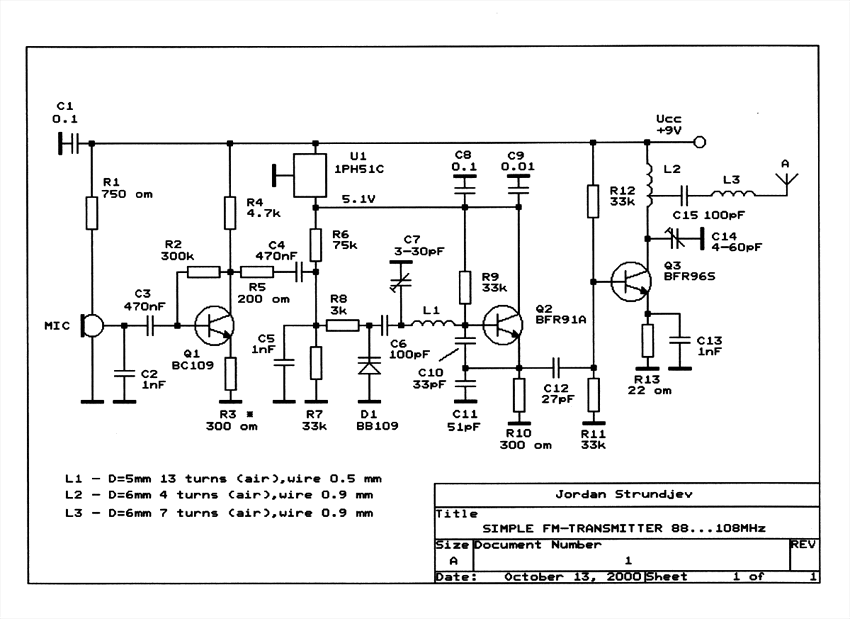
15W Fm-transmitter - Building a good
fm-transmitter(88-110Mhz) begins with getting a good
schematic. You don't have to understand the precise
working of the transmitter to build it. But some
basic information won't harm.
175kHz Inductive Pulse Transmitter - This
circuit is discussed in more detail in the
Experimenters Journal. The transmitter’s six inch
diameter coil launches powerful magnetic 175KHz ring
pulses that can be detected by the circuit below....
[Designed by David A. Johnson]
1GHZ Frequency Meter - This is 1GHz frequency
counter with 100KHz resolution. Meter is built in
around PIC16F84A microcontroller and SAB6456 /
U813BS prescaller.
1W Linear FM Booster - This RF Amplifier is
used for boosting small fm transmitters and bugs. It
use two Philips 2N4427 and its power is about 1Watt.
At the output you can drive any linear with BGY133
or BLY87 and so on. Its power supply has to give
500mA current at 12 Volts. More voltage can boost
the distance but the transistors will be burned much
earlier than usual.! In any case do not exceed the
15Volts. The Amp offers 15 dB in the area of 80Mhz
to 110 Mhz. L4, L5, and L6 are 5mm diameter air
coils, 8 turns, with wire 1mm wire diameter.
1W Portable PLL transmitter - This small FM
transmitter includes a limiter, a microphone
amplifier and a PLL digital tuning. All the parts
are placed on one circuit board. The RF power is
switchable between 1W and 0,2W....
1W RF Power Amplifier for iPOD Stereo FM
transmitters - This map, armored also enables
automatic MONO / MPX through a low-pass filter, even
with a multiplex on its entry by using an ON / ON,
panning, the whole spectrum MPX more RDS is sent to
the synthesizer, on the other hand when it is in a
position MONO, the low-pass filter is activated and
share its cutoff frequency at 15 KHz, only
modulation G + D is sent to the synthesizer, as 19
KHz. 19 KHz carrier, the signal multiplex and
subcarrier 57 KHz is thereby eliminated, which
provides ease of use for example in a string of
issue relay tuner, if the link between the issuer
Departure and receiver re-issue was not of good
quality stereo, you sufficient to switch to mono to
improve sound quality, you can then connect the RDS
encoder at the re-issuer.
2 channel RF remote control - This RF remote
control it runs at 418MHz frequency and support up
to 2 channels. It is very safety as the transmitting
code is changing every time you push any button
(roll-code function)
2 Meter Transmitter - This project is a simple
transmitter using only one crystal and will cover
145.00 to 146.00 MHz. The crystal is a 44.9333 MHz
crystal for 145.500 receive, as used in the Trio
(Kenwood) 2200, PYE, Motorola, Tait equipment, to
name but four. The frequency of the crystal is not
critical as almost any other Xtal for the 2-meter
band will function.... [from Harry Lythall's
website]
2 Transistor LED Flasher (Bill Bowden) - This
circuit will flash a bright LED (500 mcd) as an
attention getting device.
2 Transistor Transmitter (Rob van der Weijden)
- A compact 2 transistor transmitter for use at VHF
frequencies.
2 Valve 40m CW Transmitter - amateur radio
construction projects….circuit only, no description
given…. [from Peter Parker's website]
2 Valve CW Transmitter - Electroinic circuit
design…. [from Harry Lythall's website]2.x GHz WiMAX Direct Conversion Transmitter -
AN-826 Analog Devices Application Notes....[App
Note]
20W FM Amplifier - This Power amplifier is
equiped with two Philips bipolar transistors : the
BLV10 & BLW87. As lots of FM amplifier design, the
RF transistors are in a class C bias. The FM
amplifier has a 21 dB gain with a 55 to 65%
efficiency.
250mW HF CW Transmitter - Electroinic circuit
design…. [from Harry Lythall's website]
25W RF amplifier
- RF amplifier with 25W of
power for 88-108MHz FM transmitters.
27MHz AM/CW Transmitter - Electroinic circuit
design…. [from Harry Lythall's website]
27MHz toy car receiver - Electrical Engineer,
Engineer of Informatics]
27MHz Transmitters - n this discussion we cover
27MHz transmitters and receivers as found in remote
control cars, aeroplanes, walkie talkies and some of
the older-style garage door openers. We have
provided a number of circuits so you can work out
the best type for your application and these
circuits will also help you understand which
components are critical.
2N2222 40 Meter CW/DSB Transceiver - In spring
of 1998, NorCal sponsored a contest to design and
build a project using no ICs and 22 or fewer 2N2222s
as the active semiconductor devices. I thought this
was a really intriguing idea, so I set about to
design my version.
2W RF Amplifier For 24/23 CM - This page
describes TX ATV Transmitter for 23 cm with output
adjustable from 100 to 250mW.
3 Channel IR Remote Control - This project is a
3-channel IR remote control with 3 output relay and
easy to build. Features: CPU PIC12F629 at 4MHz
crystal for Tx/Rx, 3 channel output relay, The Tx
use sleep mode for saving battery power, Use
Phillips RC5 protocol, distance more than 7 m, Easy
circuit to build and assembly and small amount of
components. Uses RC5 protocol which is probably the
most used by hobbyists, probably because the wide
availability of cheap remote controls and easy to
understand.
3 Channel RF Remote Control - This is a 3
channel RF remote control project.The transmitter
powered by 3V battery(coin size) range about 10 m.
This remote control I use PIC12F509 from Microchip
which is a 8-pin single-chip microcontroller
designed for low pin count applications with 1 K
words flash memory and 41Byte SRAM and some special
features such Power-saving Sleep mode,Wake-up from
Sleep on pin change.
30 Meter QRP Transmitter for Morse Code - This
transmitters' intended purpose is for morse-code
only in 30 meter band (Tony van Roon's 10Mhz). It
is a low-power QRP type and needs to be connected to
your existing tranceiver. harmonic rejections on
prototype were measured at 40dB on 20Mhz and 50dB on
30Mhz.... [Tony van Roon's circuit]
302 MHz Prescaler - A preamp that drives the
CMOS counter input and a divide by 10 prescaler to
extend the range of A Little More Serious Frequency
Meter. The MCT10280 prescaler can be set to divide
by 80, 40, 20, or 10, as a function of which pins
are tied to the power supply. I set this one to
divide by 10 since it is adequate for my needs, and
the mental calculation of multiplying the meter
reading by 10 is not taxing. One problem with the
MCT10280 is that if it doesn't have an adequate
input, the output is very noisy, which shows up as
counts in the couple MHz range on the frequency
meter. This noise shows up if the signal amplitude
the signal frequency is too low. For this reason, I
only intend to use the prescaler with inputs between
10 MHz and 300 MHz.
303MHz TRANSMITTER with 32kHz Crystal - We have
covered 27MHz (and 49MHz) links on P1 and P2 of this
article and shown how to produce a simple circuit
(or buy a toy for less than $10.00) and get 4 or 5
channels.
We also showed how to produce on/off from a single
channel and how to detect 27MHz with a Field
Strength Meter.30m direct Conversion receiver - This simple
receiver was originally intended to check the
transmission of my 30m QRSS beacon. By tuning the
30m receiver to Russia's RWM time signal on exactly
9996kHz I was able to calibrate my frequency
counter, which I could then use to measure the
output of the QRSS beacon and adjust the reading for
a very high precision. Later, I modified my 1-valve
ECL82 CW transmitter for 30m operation and enjoyed
several QSO's on 30m CW.
30W VHF FM Amplifier for 88-108 MHz with BLF245
MOSFET - The achievement of this 30-watt
amplifier has been designed to take place on a heat
sink microprocessor PC equipped with its fans, the
advantage of this method of cooling has been
selected for the fact that
3m 100 MHz small bug
3V FM Transmitter for 88MHz to 108MHz - The
important part of the circuit is formed of the
Colpitts type oscillator. C3,C4,C5,C6,CD1-CD2 and L1
determines the frequency. BF982 and dual gate MOSFET
are active parts in oscillator. When the input
impedance of the MOSFET gate inputs are high, LC
tank is not affected. However transistors force the
LC tank and cause phase shift. Two driver stages are
added to isolate the antenna from oscillator. First
stage (BF199) amplifies the low signal of the
oscillator and works as a constant load. The second
stage (BFR90) amplifies the signal going through the
antenna some more. A short copper wire can be used
as an antenna here. Attaching a large antenna to
this circuit is unnecessary because the output power
is low.
3W FM Transmitter - This is the schematic for
an FM transmitter with 3 to 3.5 W output power that
can be used between 90 and 110 MHz. Although the
stability isn't so bad, a PLL can be used on this
circuit. This is a circuit that I've build a few
years ago for a friend, who used it in combination
with the BLY88 amplifier to obtain 20 W output
power. From the notes that I made at the original
schematic, it worked fine with a SWR of 1 : 1.05
(quite normal at my place with my antenna).
3W HF QRP Linear Amplifier - Electronic circuit
design…. [from Harry Lythall's website]
4 Transistor Transmitter - This circuit
provides an FM modulated signal with an output power
of around 500mW. The input Mic preamp is built
around a couple of 2N3904 transistors, audio gain
limited by the 5k preset. The oscillator is a
colpitts stage, frequency of oscillation governed by
the tank circuit made from two 5pF capacitors and
the inductor.... [Design by Paul K Sherby]
40 Meter, 5 Watt QRP Transmitter - As ham
operators, we like to broaden our horizons by trying
something new. There is nothing more satisfying
about this hobby than building your own transmitter.
The circuit in figure 1 is a crystal controlled CW
transmitter with at least 5 watts of power. (The
prototype generated 7 ½ watts)This circuit was built
on a Radio Shack universal board (276-168B) and
worked extremely well the first time.... [Radio
Amateur Society of Norwich]
400mW VCO FM transmitter - With good antenna
(dipole placed outdoor and high) the transmitter has
very good coverage range about 500 meters, the
maximal coverage range is up to 4 km. ....
4-20 mA Digital-to-Process Current Transmitter
- AN-21 Analog Devices Application Notes....[App
Note] Describes a 3 I.C. Digital to 4-20 mA Current
Output Circuit (DAC08, REF01 and OP221)
433MHz transmitter using SAW resonator - [Peter
Jakab, Electrical Engineer, Engineer of Informatics]
434MHz short-range communications - article
from Elektor 1998/5…. [Peter Jakab, Electrical
Engineer, Engineer of Informatics]
4-Transistor Transmitter (Paul C. Sherby) -
This circuit provides an FM modulated signal with an
output power of around 500mW. The input microphone
pre-amp is built around a couple of 2N3904
transistors (Q1/Q2), and audio gain is limited by
the 5k preset trim potentiometer. The oscillator is
a Colpitts stage, frequency of oscillation governed
by the tank circuit made from two 5pF ceramic
capacitors and the L2 inductor....
5 Channel RF AVR Remote Control - How many
times you needed some remote control to handle some
electric device ? many times. There are lot of
remote controls like infrared, RF, SMS (like my
other circuit) and more. The basic small-range
remote controls are 2, Infrared and RF (Radio
Frequency). One of the weaks of Infrared is that the
signal can not pass the walls. So, if you want to
control your garage door, the only way is to use
some RF remote control. The circuit (transmitter and
receiver) use few components and ordinary (I love
few component circuits) . Its easy to build it
because you don't have to tune-up any coil or
variable capacitor. The RF modules are fix to work
in 418MHz area.
5 watt 80 meter QRP CW Transceiver - A great
deal of interest has been generated by my previous
design articles, so I decided to go to work on a
full blown transceiver design. After several months
of work, the ROSE-80 transceiver was born. This
transceiver is similar to other designs but contains
some unique differences.
5 Watt FM Amplifier - This design is a 2 stage
amplifier that has about 17db of gain, suitable for
an input of 50 to 100 MW. Its basically a Veronica 5
watt vco transmitter, without the vco. The
transistors are a 2N4427 and a MRF237. Output power
is 2.5 to 5 watts, depending on input drive and dc
voltage. At 13.7 vdc with 50 MW of drive, the output
was 2.5 watts. The maximum dc voltage recommended is
about 15-16 volts.
5 Watt FM Transmitter with Antenna 88-108 MHz -
Two stages -- AUDIO AMPLIFIER AND OSCILLATOR and RF
POWER AMPLIFIER
5 Watt HF CW transmitter - This is a very
simple 5 watt CW TX based upon a TTL logic chip.
There is just one "tricky" component and this is Cx.
This component should have an impedance of about 10
- 50 ohms at the frequency of interest. If you wish
to reduce the transmitter power, increase the value
of Cx. It is Cx which causes the square wave from
the output transistor to approximate a sine
waveform. The value of Cx is the price of simplicity
in this TX.... [from Harry Lythall's website]
5 Watt UHF TV Amplifier - This small circuit is
a Linear amplifier for driving small UHF TV
transmitters. Its gain is 7dB and can amplify a
signal between 450-800 MHz. You can drive the
circuit with 1 to 1,5 Watts signal. Better use
double layer PCB with the second layer connected to
earth.
500mW HF Linear Amplifier - Electroinic circuit
design…. [from Harry Lythall's website]
5W PLL FM Transmitter - Easy to build
high-quality PLL FM transmitter with typical output
power of 5 W and no-tune design…....
5W PLL Stereo Transmitter with LCD - Here's PLL
FM transmitter circuit from china. This circuit
uses the familiar 2SC1971 for final power amplifier
stage.
60W Linear Amplifier - This is a RF Linear
amplifier for QRO using power mosfet IRF840 with
power out 60 Watts. It's simple all solid state
circuit. The IRF series of power transistors.
7MHz QRP Transmitter
8 Channel RF Remote Control - This is an 8
Channel RF Remote Transmitter and Receiver that will
allow to remotely control various electronic
projects. RF Remote Control provides 2 latched and 6
momentary outputs that could be used to control your
favorite devices such as amplifier, robotic devices,
RC cars, computer, home appliances, lamps and many
other cool gadgets.
80 Meter DSB Transmitter - amateur radio
construction projects…. [from Peter Parker's
website]
800 meter 2400ft range FM transmitter that fits on
top of standard 9V battery
807 & 1625 Valves - data on vacuum tubes 807
and 1625 used in ham radio transmitters. Describes
various pin voltages and different operation modes.
8W PLL Stereo Transmitter with LCD - Very
stable FM transmitter based on TSA5511 synthesizer.
Frequency is performed with three buttons through
PIC16F84 microcontroller. Frequency is displayed on
16x1 LCD.
98-108MHz FM audio transmitter Peter Jakab,
Electrical Engineer, Engineer of InformaticsA 2.x GHz WiMAX Direct Conversion Transmitter -
AN-826 Analog Devices Application Notes....[App
Note]
A 3m 100 MHz small bug
A Simple FM Stereo Transmitter
A small FM transmitter (SMD)
Achieve simple IR data transmission from a PC’s
serial port - 11-Oct-07 Issue of EDN By
transmitting appropriate hex values from a PC's
serial port to a pair of IR LEDs, a remote-control
IR receiver can enable 38.4-kHz data
transmission.... [Design Idea by Andreas Grün,
Wedemark, Germany]
ALTOIDS Tin Part 15 Version FM Transmitter -
The transmitter uses 2 MPSH10 (equiv BF494 or
NTE229) transistors in a double-ended free-running
voltage controlled oscillator (VCO) operating at
half the output frequency on each side and combined
at L2, which is tuned to the 2nd harmonic of the VCO
and covers the 88-108 MHz range. A standard 9 volt
battery is used for power and fits inside the tin.
The mono audio input circuit is totally passive with
70us pre-emphasis provided and the audio quality is
great.
AM DSB Transmitter for Hams - circuit diagram
of simple double side band suppressed carrier (DSBSC)
transmitter for hams. Circuit uses crystal
oscillator, crystal can be switched for multi band
operation......
AM FM Simultaneous Transmitter Using Digital IC
AM Transmitter - The circuit is in two halfs,
an audio amplifier and an RF oscillator. The
oscillator is built around Q1 and associated
components. The tank circuit L1 and VC1 is tunable
from about 500kHz to 1600KHz.… [Andy Collison]
AN-146: FM Remote Speaker System - National
Semiconductor Application Note
AN-21: 4-20 mA Digital-to-Process Current
Transmitter - AN-21 Analog Devices Application
Notes....[App Note] Describes a 3 I.C. Digital to
4-20 mA Current Output Circuit (DAC08, REF01 and
OP221)
AN232: Low Frequency Magnetic Transmitter Design
- Microchip Application Note Published 14-Oct-02
AN242: Designing an FCC Approved ASK RFPIC™
Transmitter - Microchip Application Note
Published 2-Jan-03....[App Note]
AN-543-Monaural FM Transmitter DSP, 20,641 bytes
- AN-543-MonauralFMTransmitter-Analog Device
Application Notes....[App Note]
AN-543-Stereo FM Transmitter DSP, 26,085 bytes
- AN-543-StereoFMTransmitter-Analog Device
Application Notes....[App Note]
AN-654: Optical Module Development Platform 2.5 GBPS
Transmitter with Digital Diagnostics - AN-654
Analog Devices Application Notes....[App Note]
AN-673: 2-Way Multiplexed LCD Drive & Low Cost
A/D-Converter using V/F Techniques with COP8
MicroControllers - National Semiconductor
Application Note....[App Note]
AN-826: A 2.x GHz WiMAX Direct Conversion
Transmitter - AN-826 Analog Devices Application
Notes....[App Note]
Antennas for HAM Transmitters - Describes how
to construct various type of antenna for Ham Radio
Transmitters.....
ATV Repeater Controllers
Automatic message sender for CB
Automatic Repeater - Circuit designed by
Miroslav Adzic. This circuit will be of interest
to radio amateur and anyone possessing two radios,
(one of which must be able to transmit i.e. a
transceiver). It is a self powered (audio derived)
repeater circuit for receiving a signal and
re-transmitting it via or radio.
Automicro TM02 high power transmitter module
schematic - [Peter Jakab, Electrical Engineer,
Engineer of Informatics]
BA1404 HI-FI Stereo FM Transmitter
- The above
FM transmitter design is a result of many hours of
testing and tweaking. The goal was simple; to test
many existing BA1404 transmitter designs, compare
their performance, identify weaknesses and come up
with a new BA1404 transmitter design that improves
sound quality, has very good frequency stability,
maximizes transmitter's range, and is fairly simple
for everyone to build. We are happy to announce that
this goal and expectations have been met and even
exceeded.
BandPass Filter - This band pass filter is in
fact a combined high- and lowpass filter. The first
stages are a high pass (f>70MHz) and the last stages
a low pass (f<180MHz). The lost of this filter is
several watts when driven with 20[Watts], but the
output signal is (when adjusted with a spectrum
analyser) very clean.
Basic RF Oscillator #1 - This basic circuit is
eash to build and the components are not critical.
Most of them can be found in your junk parts box….
[Tony van Roon's circuit]
Beeper bug transmitter for fox hunt & vehicle
tracking
BH1415F FM Stereo PLL Transmitter - This is FM
PLL Stereo based BH1415F IC from Rohm, it's has
built in PLL and Stereo Encoder. You can download
the schematic, pcb layout and Hex code. The
transmitter menu display with LCD, and this have
step 100Khz, 200Khz,....1000Khz and have Mode menu
(stereo/mono). In Action, LCD Display can solder
directly on the bottom.
BH1417 PLL Stereo Transmitter
- This is the
latest BH1417 FM Transmitter design from RHOM that
includes a lot of features in one small package. It
comes with pre-emphasis, limiter, stereo encoder,
low pass filter, PLL rock solid frequency
transmission and RF output buffer.
BH1417 Stereo PLL FM Transmitter - The new FM
Stereo Micro mitter is now crystal-locked which
means that the unit does not drift off frequency
over time. In addition, the distortion, stereo
separation, signal-to-noise ratio and stereo locking
are much improved on this new unit compared to the
earlier designs. The specifications panel has
further details....
0.1 - 3.5GHz Prescaler - This handy prescaler
divides input frequency by 1000. It takes maximum
input frequency of 3.5GHz and converts it into
3.5MHz that may be measured using standard frequency
meter.
0-500MHz PIC16F876 RF Power Meter - RF
Measurement has been an expensive work so far the
cost of measuring instruments are concerned. RF
Meter is based on PIC16F876 microcontroller, AD8307
and 2x20 LCD display. Full documentation is
included.
1 Valve CW Transmitter - This one-valve (ECL82)
CW Transmitter occupies a very special place in my
amateur radio history. I was first licensed in 1994
but did not operate on air. I committed to only
ever... [Written by Hans Summers]
1 Watt Four Stage FM Transmitter - This FM
transmitter circuit uses four radio frequency
stages: a VHF oscillator built around transistor
BF494 (T1), a preamplifier built around transistor
BF200 (T2), a driver built around transistor 2N2219
(T3) and a power amplifier built around transistor
2N3866 (T4). A condenser microphone is connected at
the input of the oscillator.

 SKEMA RANGKAIAN LAMPU LED BERJALAN
 Rangkaian Penguat Antena VHF